Back to Technical Index
Adding a Link port to the Super Gameboy
Small note: the SNES is also known as Super Famicon
Starting Idea:
The Super Game Boy is a cartridge that can be inserted into a Super Nintendo (also known as Super Famicon or SNES) like a game,
but has a slot for Gameboy cartridges on the top. That way you can play Gameboy games on your SNES using a big television instead of that
tiny gameboy screen.
As additional advantages you can add colors to your old games (some newer games even bring their own color sets), add some frames around the GB-screen
(some newer games bring those with them as well), create your own frames etc.
It is rather unknown that in truth, the SGB has a nearly complete Gameboy in it. It has a similar CPU, RAM Banks etc. The Controller-input is taken from the
SNES-Controller and Sound- and Video-Output is also given to the SNES. You may say that the "interface" has been modified, while the central functions
are the same.
Unfortunately Nintendo missed out on one kind of interface: The Super Game Boy lacks the Game Link connector. I've heard that they later released
some kind of "Super Game Boy 2" that had that connector (and also enables two player on one screen), but as the Super Game Boy 1 already has all necessary
connections (the Link Port are some pins on the GB-CPU - and the GB-CPU is very much the same as to SGB-CPU), it is very easy to add the port yourself.
You might want to compare some schemes or find out more about the Gameboy hardware. DevRS.com has some very good
ressources.
Necessary thingys
Although the Super Game Boy has all the necessary pins, a gameboy still has some more components connected to the right pins. As far as I can see,
those are rather for protecting the CPU from misconnections etc. You may want to buy them at your local electronic store, but I prefer to take them from
dead gameboys. If you browse this website, you will find some more ideas on what to do with the rest.
- The Link port connector itself
- 3 Resistors (220 Ohm)
- Some kind of "double - diodes" (due to some guides they can be replaced with two germanium diodes)
- 3 capacitors (100 picofarad)
And - or course - you will need some wires. I also recommend some soldering PCBs with connection columns.
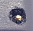
Some thing about the Connector: If you're lucky, there are some numbers printed on it. If not, here are the correct numbers.:
You should also know how to see the double-diode. At one pin there is a K or C. This is for orientation:
Of course you need to open the SGB in order to solder inside it. Opening it may be some kind of problem because it doesn't only use
some very uncommon screw (I use a screwdriver outer hexagon 3.2), the holes around the screw also are too small for screwdrivers to fit.
After trying for some time, I simply used a small drill to have some more place. That doesn't look beautiful, but I found no other way.
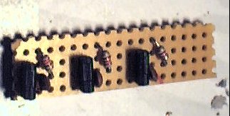
I recommend to solder a small electronics board now. You need to have the following scheme three times (so you need a 4 column, 14 row PCB).
You can leave the P and N columns connected all the way through, but you need to remove the connection at the other two lines.
Don't solder the conenctions to link port and SGB-CPU, yet. This will make things easier.
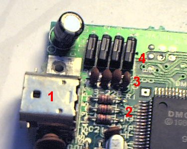
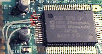
Now for the interesting part. Find the SGB-CPU on the lower side of the SGB-platine. You need to solder some wires to the pins 68, 69 and 70.
(Pin 68 is the 4th one in line)
The pins are very small, so use very small wires and very small solder!
connect each of the wires to the resistor of one of your electronics board, but remember where you connected them... It's pain to trace them back afterwards.
Of course you also need the power connections. Technically you could take them from somewhereat the CPU, too - but I prefer taking the power from the
GB connector. Pin 1 features P5V, Pin 32 is GND. On my SGB they were nicely labelled.
Now you need to connect the Link Power connector. Although the port has 6 pins, you only need 5 wires.
| Pin | Connect to |
|---|
| 1 | directly to P5V |
| 2 | to electrics for CPU-Pin 70 |
| 3 | to electrics for CPU-Pin 69 |
| 4 | do not connect |
| 5 | to electrics for CPU-Pin 68 |
| 6 | directly to GND |
You most certainly want the Link Port to be external, so you have to drill a hole in the SGB-case and lead the wires through it.
Of course, it might be a nice idea, directly connecting an old link cable internally (but still you need to drill a hole)
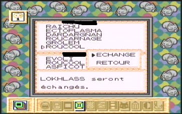
After you got all the connections, test it! put the SGB into your SNES and switch the SGB on (without Gameboy game). If it boots up correctly
and tells you that there's no game inside, insert some multiplayer-capable game. Connect the SGB to a standard Gameboy with a link cable.
When I tried this the first time, something went wrong and I got some strange color rotation. I already thought I screwed my
SNES or SGB but after some opening up and resoldering everything worked out fine.
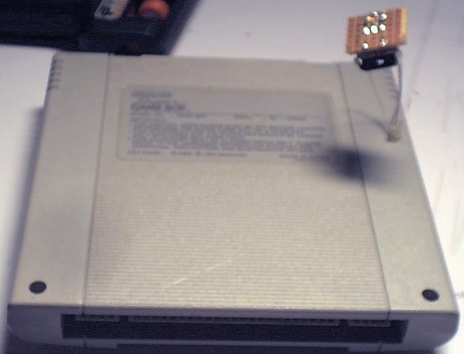
After everything worked out fine, I hot-glued the wires at the drilling hole to stabilize them some more. Then I closed the SGB.
It doesn't look really beutiful (because the Connector is some kind of flying), but it works. Perhaps you could attach the connector to the case,
so that it looks nicer and is more stable.
By the way: As the SGB looks like a normal Gameboy to the other side, it is possible to hook up two SNES with Super Gameboys. Of course,
you also need two TV sets. If anyone ever has a four-player-session with four TVs, four SNES, four modified Super Gameboys and four copies
of Super RC Pro Am (or another 4-player Racing game), I'd love to have some pictures.