Back to Technical Index
Turning a Gameboy into a PC-Game controller
Starting Idea:
It is not that uncommon any more playing gameboy games at the PC with an emulator. It simply has some nice advantages over
playing at the gameboy:
- You can Save State any time you want. Somepeople might consider this cheating.
You can try some points as often as you like until you manage to do them like you want to.
- You can play on a larger screen, mich more eye-friendly than the tiny gameboy screen
- You can give your games some colors (even better than using the Super Gameboy with an SNES).
- You can keep several savegames (as files) from a game that normally only allows one savegame (e.g. Pokemon)
- Your Gameboy batterie can't run low. (Except when you're playing on laptop)
- Some emulators have a "Speed-Up"-Key, so you can skip over long and boring sequences.
- Some emulators have "Cheater-Support" built-in (Game Genie, Game Shark, etc) so you don't need an extra module
Of course it is illegal downloading ROM images of games you don't own.
Nintendo even doesn't want you to have a backup of games you legally own. (I once read a comment on their homepage about that).
Still I think it's completely OK having a backup copy of things you bought. In many countries of the world this is even allowed by law.
I don't like Nintendo's price policy. Even games lots of years old don't fall in price (most PC games are sold for half-price after
about two or three years). Those guys started to sell "Super Mario Land" for 40 Euro (slightly more than 40$) again.
That game is about 15 years old (came out with the Gameboy 1989) and wasn't more expensive then. So you might understand why
I don't take them too seriously.
If you want to be just a tiny bit more on the legal side, buy or build your own copy station and only work with home-copied images.
I'm planning to do a guide on that, too.
Playing your games with a PC gamepad (or even the keyboard) of course is often complicated (mapping the keys) and not that fun as
playing with a real Gameboy. So I decided to open up an old Gameboy and connect it to the PC.
The PC Gameport (easily) supports 4 axis and 4 buttons. The Gameboy has two axis (up-down and left-right) and 4 Buttons (A, B, START and SELECT)
so it will be easily accepted as a 4-button gamepad. Any game accepting Gamepads will also accept such a modified Gameboy.
So you're not limited to GB-Emulators but can play a lot of games with it, too. It's also accepted by Windows98 so I believe it won't
be any problem with other Windows versions or other Operating Systems supporting the Gameport.
This is my first try of building such an adapter:
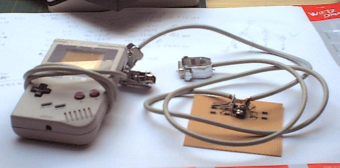
I just stripped the necessary cables out of the Gameboy, connected them to a board with the necessary circuits and then
connected them to the PC (to a 15-pin connector that can be plugged into the Gameport - to be correct)
Of course this is not the best option. That's why I decided to build another one with the circuits hidden inside the GB and only the cable coming out.
The real thing
First of all you should read the guide about connecting C64-joysticks to PC. Basically the scheme is the same but the Gameboy uses four buttons.
I like to use defect Gameboys for this. I just don't feel good at destroying working hardware. I also think that the "classic" Gameboy is the best
choice as both pocket and color are too tiny for my taste. I just can't hold them in my hands enough to play with them. Perhaps you might want to test them
out yourself. The Gameboy Advance has more than 4 buttons so you'd have to leave some unconnected. So this guide is for tranforming the "classic" Gameboy.
One of the best places for defect hardware is EBay and fairs - although it sometimes seems that working gameboys are cheaper.
You could also ask some friends, classmates, etc.
The first step will be opening the gameboy. Unfortunately Nintendo uses uncommon screws. They are called "Triwing" (because they have three wings).
You could try to find a special screwdriver or you could drill the screws out/in (Normally you drill the screws so far into the case that they
are behind what they are supposed to hold). I have some kind of "special" screwdriver: Some piece broke out of a normal screwdriver but
the remaining part seems to sometimes work. Still, I had to drill one or another screw when experimenting.
There are six screws on the back side. Two are hidden behind the "battery hider". In order to open the gameboy completely, you have to remove a small
connection cable.
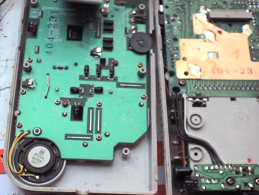
Now unscrew the boards from the right part of the gameboy (used to be the lover part - with the batteries). Perhaps you might want to use them for something
- The GamePak connector can be used to build a backup device
- The sound platine or the connector - it's stereo
- The Game-Link connector - there are some tools that let you print to PC with that.
- There are some voltage converter on the board.
- Perhaps you might want to experiment with the processor. There are a lot of tutorials for it.
For our purpose it just isn't needed any more. You might want to keep the screws in order to replace the Triwings.
Leave the metal plate in there. We will use it later.
After that unscrew the board on the left side. (There are 10 screws) You should now see the 8 buttons of the gameboy. If you follow their way on the
PCB you wil lnotice that they lead under the display. We wouldn't have kept that display anyway, so we are gonna cut it.
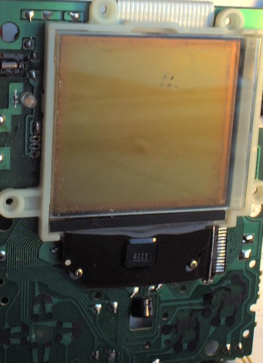
There are two tiny screws at the display, remove them.
After that you should be able to flip the display a bit. (apply some pressure from the back if necessary).
There should be another tiny screw hidden down there. Unscrew it, too.
Now you should be able to pull off the upper connection cable (ripping it from the board). It's a cruel thing to do, I admit.
On the lower right, ripping isn't that easy, so simply cut that flat cable at its shortest part. I know that this isn't less cruel.
Technically you could throw away the display, now. I like to keep it and put it back later on. That way, my cables are hidden and I can put some
paper (like "Game-Boy-PC-Controller") between glass and display.
Still that white display holder is blocking our way. So push it out from behind. Keep it with the display.
There also is that white ribbon cable connected to the top. Unsolder it. You could tear it off but we still need the contacts, so better be careful.
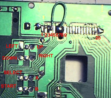
Now we need to solder some connections to the pads at the top. You should now that the Gameboy has a kind of matrix for its buttons. It is like it has several GNDs.
- Pad 7 is responsible for UP and SELECT
- Pad 4 is responsible for LEFT and B
- Pad 6 is responsible for DOWN and START
- Pad 8 is responsible for RIGHT and A
As we only need one GND, we solder them together. I put a larger Solder spot on 6,7 and 8 and put a small wire to pad 4. I am not sure, but it should suffice putting
a large solder blob connecting 4 - 8. I believe Pad 5 won't interfere with our plans.
Now we need a place to grab the button status from. You will notice 4 rows of each 3 solder points next to each other. That is where we can best solder our wires to.
(we ignore the center and only use the left and right spots)
| from the lower side |
|---|
| row | position | function |
|---|
| 1 | left | LEFT |
| 1 | right | UP |
| 2 | left | DOWN |
| 2 | right | RIGHT |
| 3 | left | SELECT |
| 3 | right | A |
| 4 | left | START |
| 4 | right | B |
| from the upper side |
|---|
| row | position | function |
|---|
| 1 | left | UP |
| 1 | right | LEFT |
| 2 | left | RIGHT |
| 2 | right | DOWN |
| 3 | left | A |
| 3 | right | SELECT |
| 4 | left | B |
| 4 | right | START |
Unfortunately those places are occupied already, so we need to remove the previous owners of those spots. If you look at the other side, they are labeled
DA1 to DA4. They are some kind of double-diodes. Read some Gameboy technical documentation if you want to know more about it. (perhaps you want to use them somewhere).
If you hadn't prepared two digital-to-analog-circuits, yet (like in the C64-PC-adapter), now would be a good time.
Push the transistors as far down as possible. They need to be as high as the potentiometers or lower.
Now connect the direction buttons to the axis converters.
Connect the "real" buttons (A,B,SELECT,START) directly to the cable to the
DSub-15-plug. (I chose A=1 B=2 START=3 SELECT=4). Perhaps you might want to use switches or jumpers to make this changeable.
Connect the GND from the cable (DSub15.4) to our solder blob. I like to put the wire through the "No Screw here" hole, it is directly under
the blob.
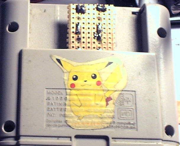
At that point you can put the platine back into the case. This is my proposal for beautifying everything:
- Put back the display holder
- Put back the screws (you might want to tighten the display with it. I chose not to)
- Put back the display.
- You might want to put a nice paper on the display, stating that this gameboy is no gameboy any more. You could put your logo on it. Do what you feel.
- put the board back into the case.
- tighten the ten screws. You should be able to press the buttons like before you opened the gameboy
- be careful with the small speaker. For real beauty make sure, it is in place before tightening the board. Perhaps you want to attack something to the speaker.
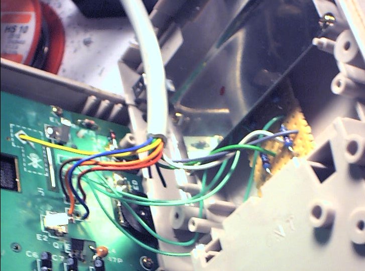
Now connect the Axis wires to the converter as usual.
Insert your own wire colors (my combination is some kind of industry standard I like to use)! Alignment on Gameboy platine is from upper side (where you put the cables)
| pin | function | connect to | My wire color |
|---|
| 1 (+9) | P5V | solder to PCB at one P5V connection point | white |
| 2 | Button 1 | row 3,left at gameboy platine | brown |
| 3 | Axis 1 (X1) | solder to PCB at output for x-axis | green |
| 4 (+5) | GND | the GND-blob at the gameboy platine | yellow |
| 5 (+4) | GND | bridge to DSub15.4 |
| 6 | Axis 2 (Y1) | solder to PCB at output for y-axis | grey |
| 7 | Button 2 | row 4,left at gameboy platine | pink/orange |
| 8 | (P5V) | Do not connect |
| 9 (+1) | P5V | bridge do DSub15.1 |
| 10 | Button 3 | row 3,right at gameboy platine | blue |
| 11 | Axis 3 (X2) | Do not connect |
| 12 | (GND) | Do not connect |
| 13 | AXIS 4 (Y2) | Do not connect |
| 14 | Button 4 | row 4,right at gameboy platine | red |
| 15 | (P5V) | Do not connect |
If you have all connections, here's another proposal for beautify: Remember that metal cover in the back of the Gameboy case?
I put the converter PCB right under it (that's why the transistors shouldn't be too high. Of course still it won't fit perfectly but the pressure from the plate
makes sure the PCB can't fall out or something.
Before you close that metal plate again, make sure that the controller is working (now is the time to connect to a tester or PC) and that the
trimmers are centered.
Your PC cable has to leave the gameboy somewhere. At first try I led it under the metal plate but then I thought it is much more convenient using
the small hole where the power switch was.
Now you can close the gameboy and put back the screws. It might be a good idea not to use the Triwing but some other screws (which are easier to open).
You should tape the module slot closed. Usually some part of the PCB still is there and you don't want to accidently short-circuit the
lines with your fingers. Still, you might think of using another Digital-To-Analog circuit design that is small enough to hide it all inside the Gameboy.
It might be a nice idea putting the digital-analog-circuit into an old module that can be plugged into the Gameboy like a real game. Then you need to connect
the 9 connections to the gameboy platine to the module holder. On the one hand I cancelled that idea because your construction has to be REAL small
(a gameboy module is very small), perhaps you have to use SMD elements, bend the transistors or use two 50k-resistors instead of the Potis. Also you have to be sure
that the "normal" Gameboy circuits don't interfere with your plans (perhaps you could isolate the module connector and saw the rest off). I'm not sure
if there is enough space for the cables (removing the module connector gave me a lot of free space).
Also it's some kind of security issues: If you have children in your house (don't even need to be children), they will put that adapter-cartridge into a
real gameboy sooner or later. (Or put a real cartridge game into your manipulated gameboy). While one of these cases seems to be harmless, the other one
might damage gameboy and/or PC. So there's a real danger you'd take just for cosmetical reasons. I don't think, being able to remove the module from the gameboy
is worth that risk.